How to build ESP32-based automatic car wash system
Components used:
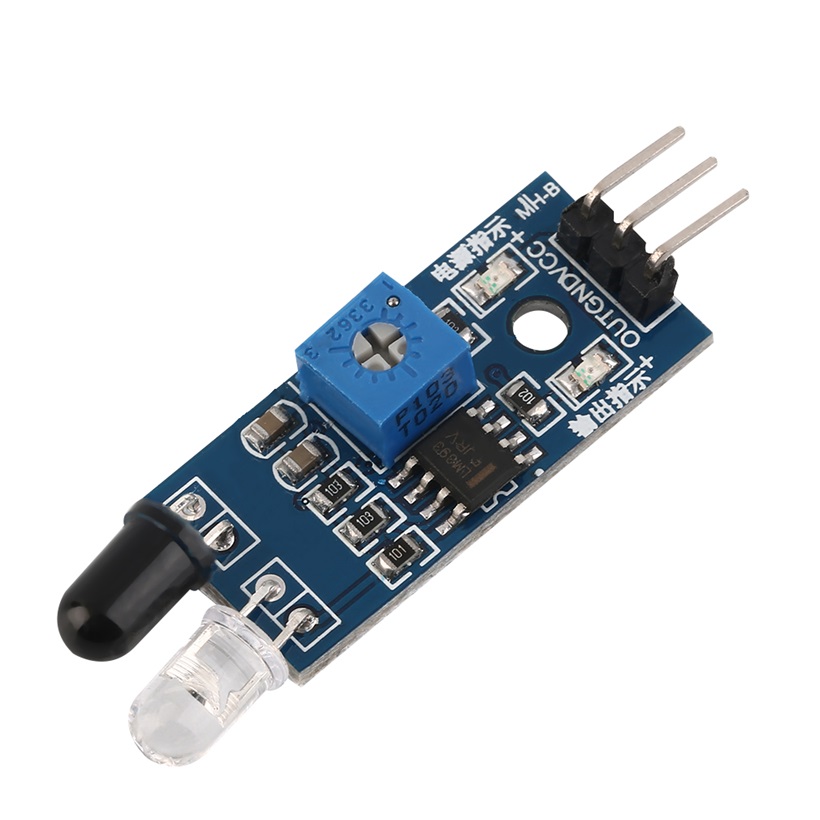 Infrared Obstacle Avoidance Tracking Sensor Module
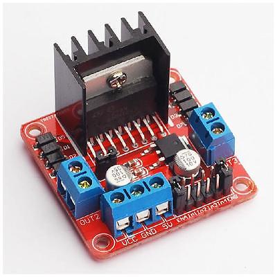 L298N Motor Driver
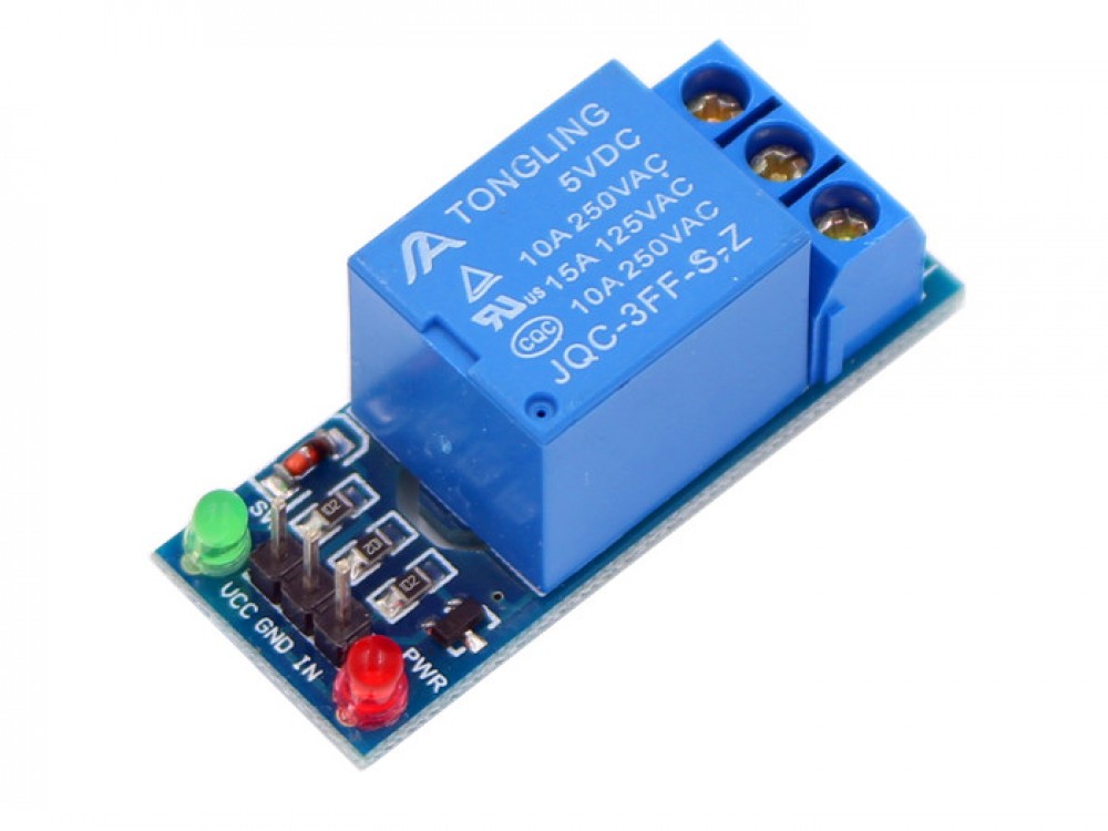 Single Channel 5v Relay Module
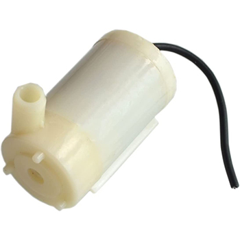 SUBMERSIBLE WATER PUMP DC 3V-5V
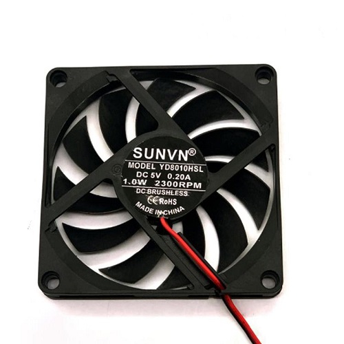 YD8010 Cooling Fan 5V
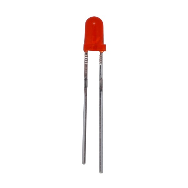 3MM LED Red
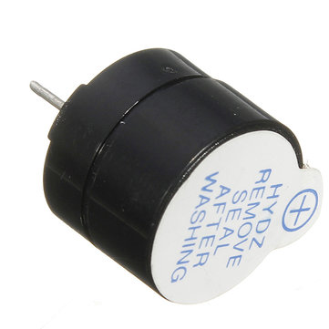 5V active buzzer
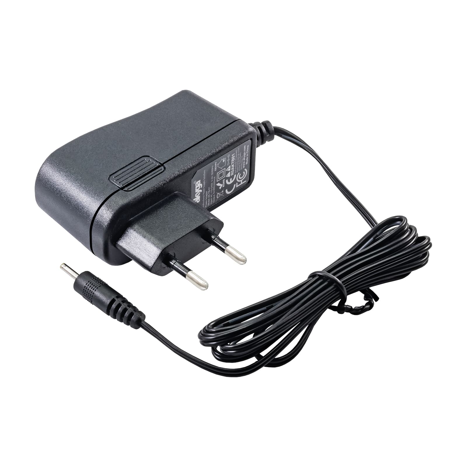 5V 2A Power Adapter
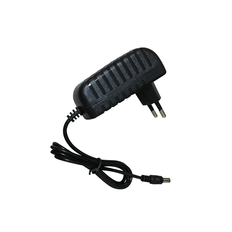 12VDC 2A Adapter charger
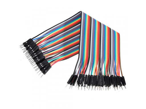 Male to Male Jumper Wires
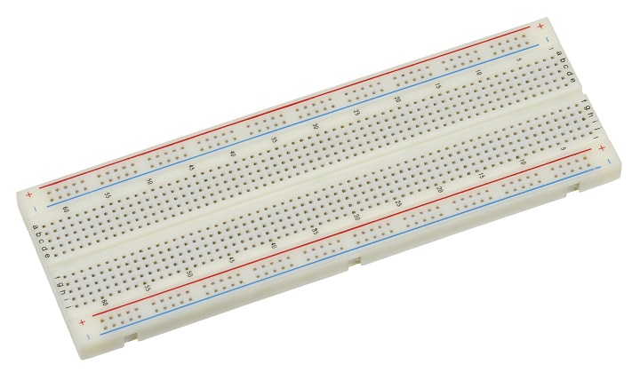 Breadboard 830 Point Solderless
terminal blocks or connectors
one main power switch
one fuse for power protection
and mounting hardware such as screws
nuts
standoffs
Breadboard 830 Point Solderless
terminal blocks or connectors
one main power switch
one fuse for power protection
and mounting hardware such as screws
nuts
standoffs
📖 Overview
This course will guide you through building an ESP32-based automatic car wash system, where you'll learn to design and implement a complex IoT project using a microcontroller. The system will utilize various sensors and actuators to automate the car wash process, including infrared sensors to detect vehicles, DC motors to move the vehicle and rotate brushes, and water pumps to spray soap and clean water.
Throughout the course, you'll gain hands-on experience with ESP32 programming, circuit design, and system integration. You'll learn how to read sensor data, control motors and pumps, and implement a state machine to manage the washing process. You'll also understand how to use a relay module to isolate the microcontroller from high-current devices and how to implement a cooling fan to dry the vehicle after rinsing.
The skills you'll acquire in this course are highly valuable in the field of IoT and embedded systems, where automation and sensor integration are increasingly important. By the end of the course, you'll have a fully functional automatic car wash system and a deep understanding of how to design and implement complex IoT projects using the ESP32 microcontroller. Some of the key topics covered include:
- ESP32 programming and circuit design
- Sensor integration and data processing
- Motor control and pump operation
- Relay module usage and system integration
- State machine implementation and automation
This course is ideal for intermediate learners who have a basic understanding of programming and electronics, but want to take their skills to the next level by building a complex IoT project. By the end of the course, you'll have a unique project to showcase your skills and a solid foundation for further exploration in the field of IoT and embedded systems.
🔌 Components & Wiring Guide
Components and Their Purposes
- ESP32 Development Board: Acts as the main controller of the automatic car wash system
- Infrared Obstacle Sensors (3): Detect the vehicle's position and trigger washing stages
- Dual H-Bridge Motor Driver Module: Controls the conveyor and brush DC motors
- 2-Channel 5V Relay Module: Isolates the ESP32 from the higher-current water pumps
- Conveyor DC Motors (2): Move the vehicle through the washing tunnel
- Brush DC Motors (3): Rotate the cleaning brushes to scrub the vehicle
- Soap Water Pump: Sprays soap onto the vehicle
- Clean Water Pump: Rinses soap from the vehicle
- DC Cooling Fan: Dries the vehicle after rinsing
- LED Indicator: Indicates system operation and status
- 5V Active Buzzer: Sounds to signal events like car detection and washing completion
- 5V Power Supply: Powers the ESP32, infrared sensors, relay module, and motor driver logic
- Motor Power Supply (12V): Powers the DC motors and water pumps
- Connecting Wires: Connect components according to the wiring guide
- Breadboard or PCB: Provides a base for connecting and organizing components
- Terminal Blocks or Connectors: Securely connects wires to components
- Main Power Switch: Controls the overall power supply to the system
- Fuse: Protects the system from power surges and overcurrent conditions
- Mounting Hardware: Secures components in place for reliable operation
Wiring and Connection Guide
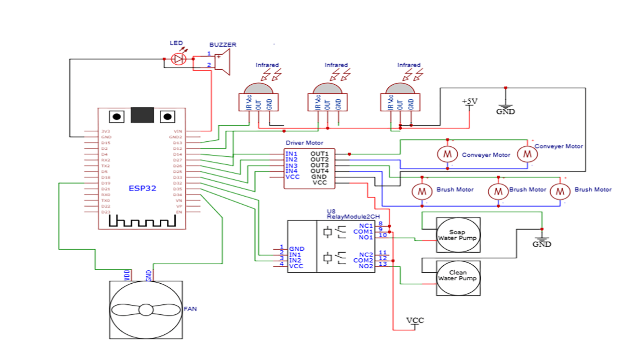
To connect the components, follow these steps: First, connect the ESP32 Development Board to the power supply. The VIN pin of the ESP32 should be connected to the 5V power supply. Next, connect the infrared obstacle sensors to the ESP32. Each sensor has three pins: VCC, GND, and OUT. Connect the VCC pin of each sensor to the 5V power supply, the GND pin to the common ground, and the OUT pin to a GPIO input on the ESP32. Then, connect the dual H-Bridge motor driver module to the ESP32. The control inputs (IN1, IN2, IN3, IN4) of the motor driver should be connected to GPIO outputs on the ESP32. The VCC pin of the motor driver should be connected to the 5V power supply, and the GND pin to the common ground. The conveyor DC motors should be connected in parallel to the outputs (OUT1, OUT2) of the motor driver. The brush DC motors should be connected to the outputs (OUT3, OUT4) of the motor driver. The 2-channel 5V relay module should be connected to the ESP32. The control inputs (IN1, IN2) of the relay module should be connected to GPIO outputs on the ESP32. The VCC pin of the relay module should be connected to the 5V power supply, and the GND pin to the common ground. The normally open (NO) contacts of the relay module should be connected to the soap water pump and clean water pump, respectively. The soap water pump and clean water pump should be connected to the power supply through the relay module. The DC cooling fan should be connected directly to an ESP32 GPIO or through a transistor/MOSFET driver if it draws significant current. The LED indicator and 5V active buzzer should be connected together to a GPIO output on the ESP32. Finally, connect all grounds together (ESP32, motor driver, relay module, and motor supply) to provide a common reference.| Component | Connection |
|---|---|
| ESP32 VIN | 5V Power Supply |
| Infrared Sensors VCC | 5V Power Supply |
| Infrared Sensors GND | Common Ground |
| Infrared Sensors OUT | ESP32 GPIO Input |
| Motor Driver VCC | 5V Power Supply |
| Motor Driver GND | Common Ground |
| Motor Driver Control Inputs | ESP32 GPIO Outputs |
| Conveyor Motors | Motor Driver Outputs (OUT1, OUT2) |
| Brush Motors | Motor Driver Outputs (OUT3, OUT4) |
| Relay Module VCC | 5V Power Supply |
| Relay Module GND | Common Ground |
| Relay Module Control Inputs | ESP32 GPIO Outputs |
| Soap Water Pump | Relay Module Output (NO1) |
| Clean Water Pump | Relay Module Output (NO2) |
| DC Cooling Fan | ESP32 GPIO or Transistor/MOSFET Driver |
| LED Indicator and Buzzer | ESP32 GPIO Output |
🛠️ Step-by-Step Guide
Step 1: Setup and Preparation
To begin, ensure all the necessary hardware components are available. The ESP32 Development Board, infrared sensors, motor driver module, relay module, motors, pumps, fan, buzzer, LED, and power supplies are crucial for the project. Familiarize yourself with the specifications and pinouts of each component to facilitate a smooth assembly process.
Step 2: Wiring the Components
Start by connecting the ESP32 to the infrared sensors, motor driver module, relay module, and other peripherals. The wiring should be neat and organized to prevent errors and shorts.
- Connect the infrared sensors to the ESP32, ensuring VCC is connected to 5V, GND to common ground, and OUT to an appropriate GPIO input on the ESP32.
- Connect the motor driver module to the ESP32, with IN1, IN2, IN3, and IN4 connected to ESP32 GPIO outputs, and VCC to 5V and GND to common ground.
- Connect the relay module to the ESP32, with IN1 and IN2 connected to ESP32 GPIO outputs, VCC to 5V, and GND to common ground.
- Connect the motors, pumps, and fan to their respective outputs on the motor driver and relay modules.
Step 3: Wiring Recap and Verification
Before proceeding, verify that all connections are correct and secure. Double-check the wiring against the component specifications and the project's circuit diagram to ensure accuracy.
- Verify the power supply connections to the ESP32, motor driver, relay module, and other components.
- Check the ground connections to ensure all components share a common ground reference.
- Confirm the control signal connections from the ESP32 to the motor driver and relay modules.
Step 4: Firmware Development and Upload
Develop the firmware for the ESP32 using a suitable development environment such as the Arduino IDE or PlatformIO. The firmware should read the infrared sensors, control the motors, pumps, fan, buzzer, and LED based on the sensor inputs and the washing cycle.
Example code snippets may include digitalRead() for sensor inputs and digitalWrite() for controlling outputs.
Upload the firmware to the ESP32 using the chosen development environment and ensure the board is properly configured for the upload process.
Step 5: Testing and Validation
With the firmware uploaded, proceed to test the automatic car wash system. Place a vehicle or a mock object in the washing area and observe the system's operation.
- Test the infrared sensors by blocking the beam with an object and verifying the ESP32 responds correctly.
- Verify the conveyor motors start and stop as expected, moving the vehicle through the washing tunnel.
- Check the brush motors rotate during the washing stage.
- Test the soap and clean water pumps, ensuring they activate and deactivate as programmed.
- Verify the fan operates during the drying stage.
- Check the buzzer and LED indicators for proper operation.
Step 6: Troubleshooting Tips
If issues arise during testing, refer to the following troubleshooting tips:
- Verify all connections are secure and not damaged.
- Check the power supply to ensure it can handle the total system current.
- Review the firmware code for logical errors or incorrect pin assignments.
- Use a serial monitor or debugger to inspect the ESP32's output and sensor readings.
- Consult the component datasheets for specifications and operating conditions.
💻 Sample Code
/*
   ESP32 Automatic Car Wash System
   Features:
   - Vehicle detection using IR sensors
   - Conveyor movement
   - Brush motors
   - Soap spraying
   - Water rinsing
   - Drying fan
   - LED and buzzer indicators

*/

// ---------- Sensor Pins ----------
#define IR_ENTRY   34
#define IR_WASH    35
#define IR_EXIT    32


// ---------- Motor Driver Pins ----------
#define CONVEYOR_IN1 25
#define CONVEYOR_IN2 26

#define BRUSH_IN3 27
#define BRUSH_IN4 14


// ---------- Relay Pins ----------
#define SOAP_PUMP 12
#define WATER_PUMP 13


// ---------- Output Pins ----------
#define FAN_PIN 33
#define LED_PIN 2
#define BUZZER 4


// Washing states
enum WashState {
  IDLE,
  MOVE_TO_WASH,
  SOAP_STAGE,
  RINSE_STAGE,
  DRY_STAGE,
  COMPLETE
};


WashState state = IDLE;


void setup() {

  Serial.begin(115200);


  // Sensors
  pinMode(IR_ENTRY, INPUT);
  pinMode(IR_WASH, INPUT);
  pinMode(IR_EXIT, INPUT);


  // Motor driver
  pinMode(CONVEYOR_IN1, OUTPUT);
  pinMode(CONVEYOR_IN2, OUTPUT);

  pinMode(BRUSH_IN3, OUTPUT);
  pinMode(BRUSH_IN4, OUTPUT);


  // Relays
  pinMode(SOAP_PUMP, OUTPUT);
  pinMode(WATER_PUMP, OUTPUT);


  // Outputs
  pinMode(FAN_PIN, OUTPUT);
  pinMode(LED_PIN, OUTPUT);
  pinMode(BUZZER, OUTPUT);


  stopAll();


  Serial.println("Automatic Car Wash Ready");

}


void loop() {


  switch(state)
  {


    // -------------------------
    // Waiting for car
    // -------------------------

    case IDLE:

      if(digitalRead(IR_ENTRY)==LOW)
      {
        Serial.println("Vehicle detected");

        beep();

        state = MOVE_TO_WASH;
      }

    break;


    // -------------------------
    // Move vehicle into tunnel
    // -------------------------

    case MOVE_TO_WASH:


      conveyorForward();


      if(digitalRead(IR_WASH)==LOW)
      {
        stopConveyor();

        Serial.println("Car in washing position");

        state = SOAP_STAGE;
      }


    break;


    // -------------------------
    // Soap washing
    // -------------------------

    case SOAP_STAGE:


      Serial.println("Applying soap");


      brushOn();

      digitalWrite(SOAP_PUMP,HIGH);


      delay(5000);


      digitalWrite(SOAP_PUMP,LOW);


      state = RINSE_STAGE;


    break;


    // -------------------------
    // Clean water rinse
    // -------------------------

    case RINSE_STAGE:


      Serial.println("Rinsing");


      digitalWrite(WATER_PUMP,HIGH);

      delay(5000);


      digitalWrite(WATER_PUMP,LOW);


      state = DRY_STAGE;


    break;


    // -------------------------
    // Drying stage
    // -------------------------

    case DRY_STAGE:


      Serial.println("Drying vehicle");


      brushOff();


      digitalWrite(FAN_PIN,HIGH);


      delay(7000);


      digitalWrite(FAN_PIN,LOW);


      state = COMPLETE;


    break;


    // -------------------------
    // Move car out
    // -------------------------

    case COMPLETE:


      Serial.println("Complete");


      beep();


      conveyorForward();


      if(digitalRead(IR_EXIT)==LOW)
      {

        stopConveyor();


        Serial.println("Vehicle exited");


        state = IDLE;

      }


    break;


  }


}


// =================================================
// MOTOR FUNCTIONS
// =================================================


void conveyorForward()
{

  digitalWrite(CONVEYOR_IN1,HIGH);
  digitalWrite(CONVEYOR_IN2,LOW);

}


void stopConveyor()
{

  digitalWrite(CONVEYOR_IN1,LOW);
  digitalWrite(CONVEYOR_IN2,LOW);

}


void brushOn()
{

  digitalWrite(BRUSH_IN3,HIGH);
  digitalWrite(BRUSH_IN4,LOW);

}


void brushOff()
{

  digitalWrite(BRUSH_IN3,LOW);
  digitalWrite(BRUSH_IN4,LOW);

}


// =================================================
// SYSTEM CONTROL
// =================================================


void stopAll()
{

  stopConveyor();

  brushOff();

  digitalWrite(SOAP_PUMP,LOW);

  digitalWrite(WATER_PUMP,LOW);

  digitalWrite(FAN_PIN,LOW);

  digitalWrite(LED_PIN,LOW);

}


void beep()
{

 digitalWrite(BUZZER,HIGH);

 digitalWrite(LED_PIN,HIGH);

 delay(500);

 digitalWrite(BUZZER,LOW);

 digitalWrite(LED_PIN,LOW);

}
📝 Check Your Understanding
1. What is the main function of the ESP32 in the automatic car wash system?

A. To supply power to all motors
B. To act as the main controller that reads sensors and controls devices
C. To clean the vehicle manually
D. To replace the water pump

Answer: B
Explanation: The ESP32 works as the brain of the system. It processes sensor inputs and controls motors, pumps, relays, LEDs, and other actuators.

2. Which sensor is used to detect the vehicle position inside the car wash system?

A. Temperature sensor
B. Infrared obstacle sensor
C. Gas sensor
D. Pressure sensor

Answer: B
Explanation: Infrared sensors detect the presence and position of the vehicle at different stages, such as entry, washing position, and exit.

3. Why is a relay module used to control the water pumps?

A. To increase the ESP32 processing speed
B. To protect the ESP32 from high current loads
C. To measure water temperature
D. To provide internet connectivity

Answer: B
Explanation: Relays electrically isolate the ESP32 from high-power devices like pumps, allowing safe switching of higher voltage and current loads.

4. What programming concept is used to manage different washing stages such as soap, rinse, and drying?

A. Random number generation
B. State machine implementation
C. Image processing
D. Database management

Answer: B
Explanation: A state machine organizes the washing process into different states, allowing the ESP32 to execute each stage in the correct order.

5. Which component is responsible for drying the vehicle after rinsing?

A. Cooling fan
B. Soap pump
C. Infrared sensor
D. Motor driver

Answer: A
Explanation: The cooling fan blows air onto the vehicle after the rinse stage to remove water and complete the drying process.
Need the Components for This Project?
If you don't already have the components listed above, you can buy genuine Arduino, ESP32, Raspberry Pi, sensors, and other electronic components from SoftTech Supply Shop, with fast delivery across Kigali and other parts of Rwanda.
← Browse more Arduino & IoT tutorialsRelated Tutorials
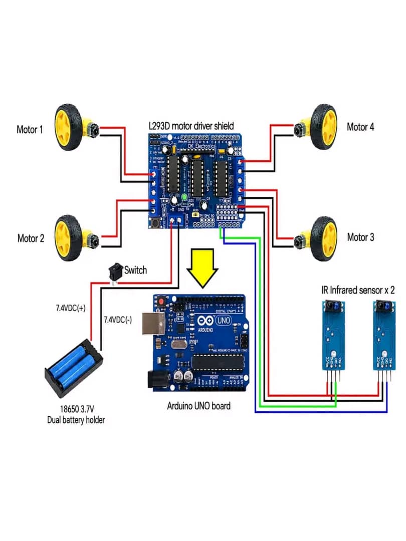
How to build a line tracking robot using Arduino UNO AND infrared sensor
Arduino Uno R3 With USB Cable, L293D Motor Driver Board, DC Gear Motor+wheels smart car set, TCRT5000 Infrared Reflective IR Photoelectric Line Track Sensor Module, 3.7V 3 Slot 18650 Battery holder, Rocker Switch Spst, 18650 3.7V 2800mAh Lithium Ion Battery
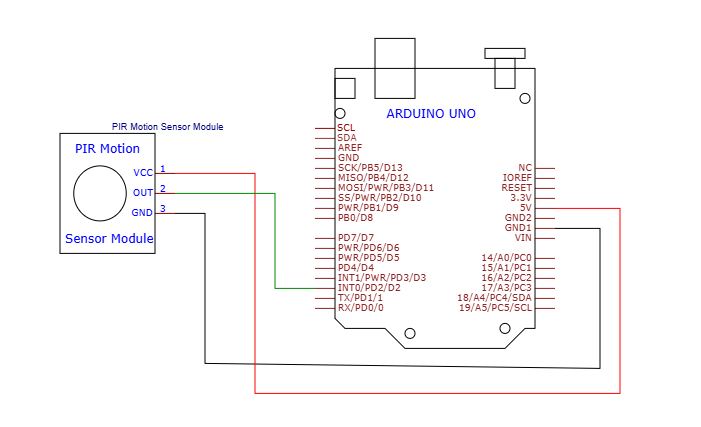
How to Use the HC-SR501 PIR Motion Sensor Module with an Arduino Uno
Arduino Uno R3 With USB Cable, Male to Male Jumper Wires, Breadboard 830 Point Solderless, HC-SR501 PIR module Sensor Detector Module
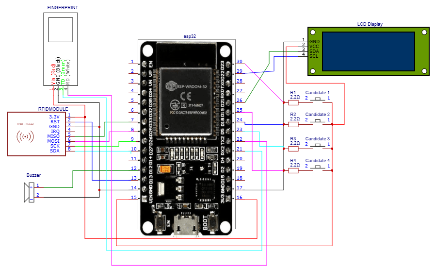
How to build an ESP32-based electronic voting system
ESP32 ESP-32 Wireless WiFi Bluetooth Development Board, 16x2LCD Display with I2C Interface, 5v active buzzer, RFID Reader Module 13.56Mhz, Push Button with cap, AS608 Fingerprint Reader Sensor Module Optical
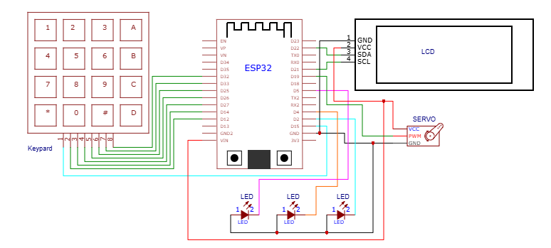
How to build an ESP32-based door access control system using keypad for password authentication
ESP32 ESP-32 Wireless WiFi Bluetooth Development Board, 4 * 4 Matrix Array Matrix Keypad, SG90 9g Mini Micro Servo Motor, 16x2LCD Display with I2C Interface, 3MM LED Red