How to build an ESP32-based electronic voting system
📖 Overview
This course will guide you through building an ESP32-based electronic voting system, a project that combines multiple hardware components to create a secure and user-friendly voting experience. The system consists of an RFID module for voter authentication, push buttons for candidate selection, a fingerprint sensor for identity verification, an I2C LCD display for instructions and status updates, and a buzzer for audio feedback.
By the end of this course, you will have learned how to integrate these components with the ESP32 microcontroller to create a functional electronic voting system. You will gain hands-on experience with RFID and fingerprint sensor technologies, as well as learn how to interface with I2C devices and implement a user-friendly interface using push buttons and an LCD display.
The skills and knowledge gained in this course will be useful for a variety of applications beyond electronic voting systems, such as access control, identity verification, and user authentication. You will also learn about the importance of security and verification in electronic voting systems, and how a two-factor authentication system can help prevent voter fraud.
Key topics covered in this course include:
- Setting up and configuring the ESP32 development board
- Interfacing with RFID and fingerprint sensor modules
- Implementing a user-friendly interface using push buttons and an LCD display
- Integrating audio feedback using a buzzer
- Writing code to manage the voting process and record votes
This course is designed for beginners with basic knowledge of electronics and programming, and will provide a comprehensive introduction to the world of IoT and embedded systems development using the ESP32 microcontroller.
🔌 Components & Wiring Guide
Components and Their Purposes
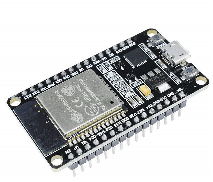
- ESP32 Board: The main processing unit of the electronic voting system
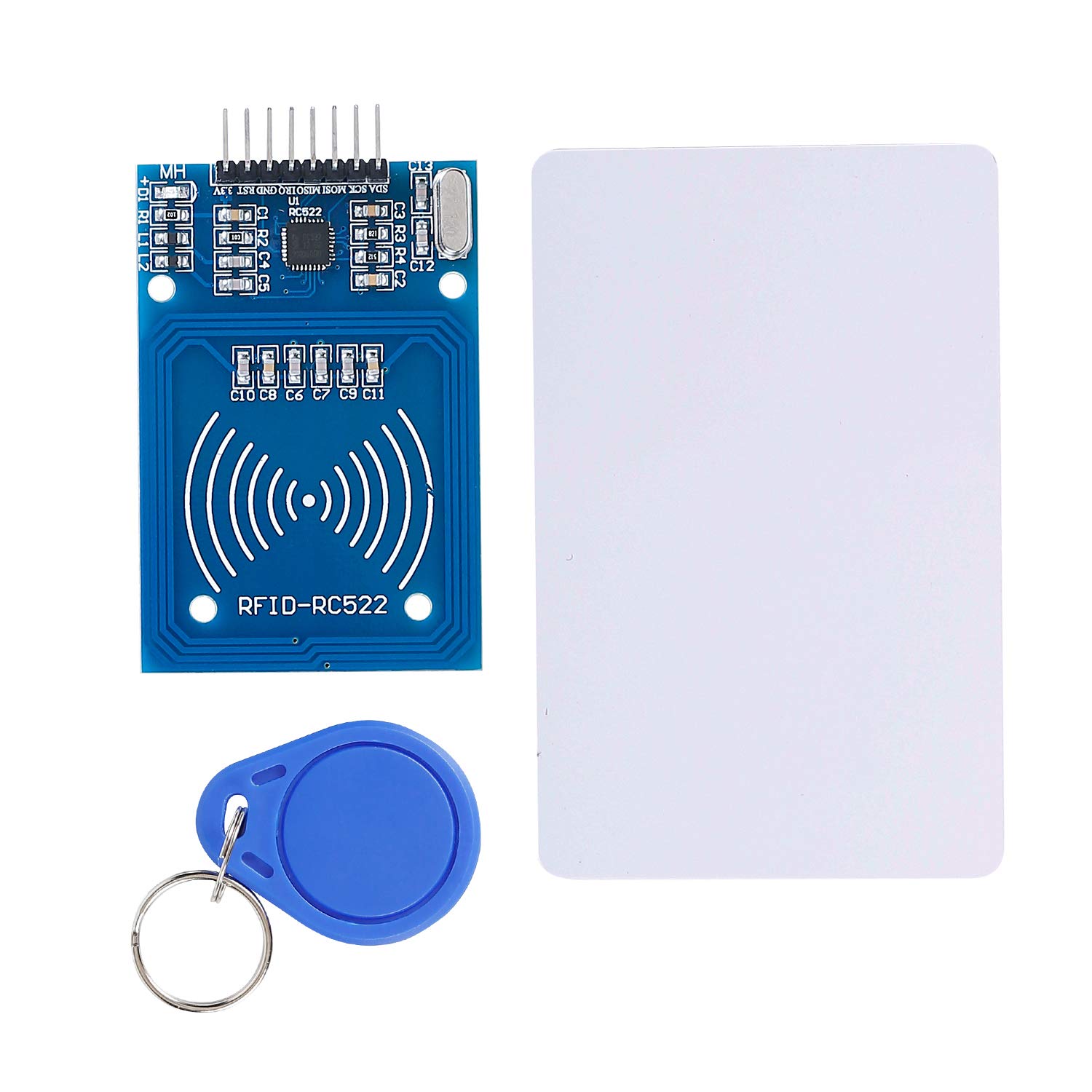
- MFRC522 (RFID Module): Initializes and authenticates the voting session
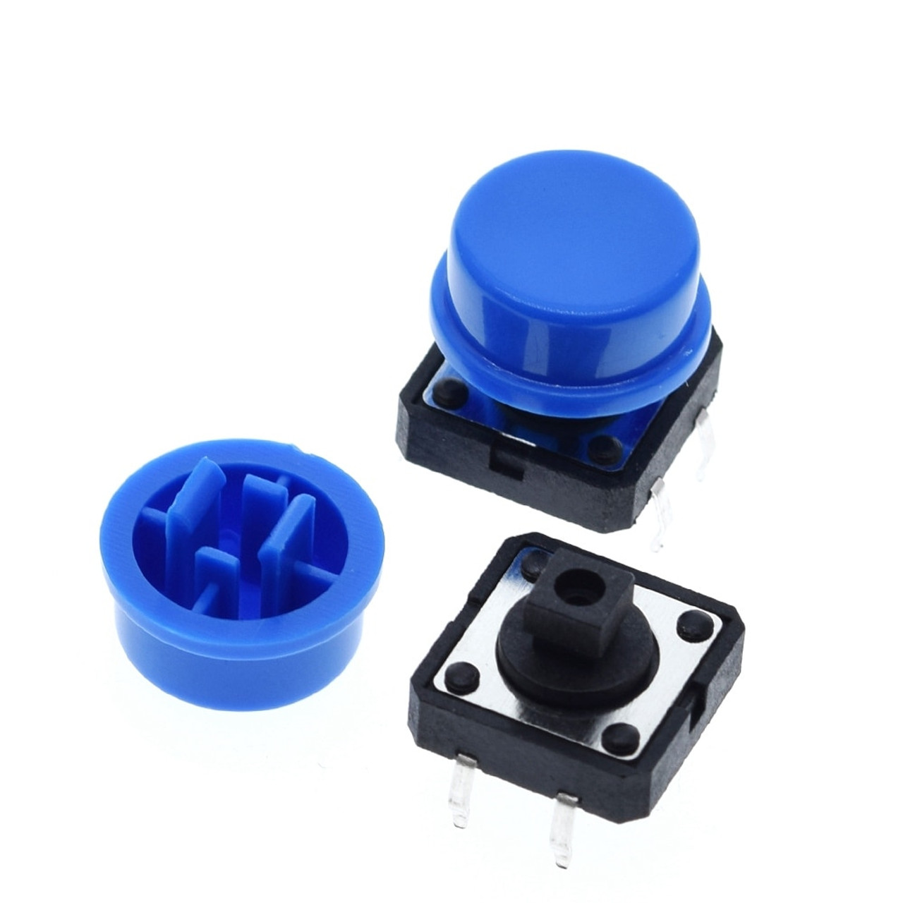
- 4 Push Buttons: Allow the citizen to select a candidate
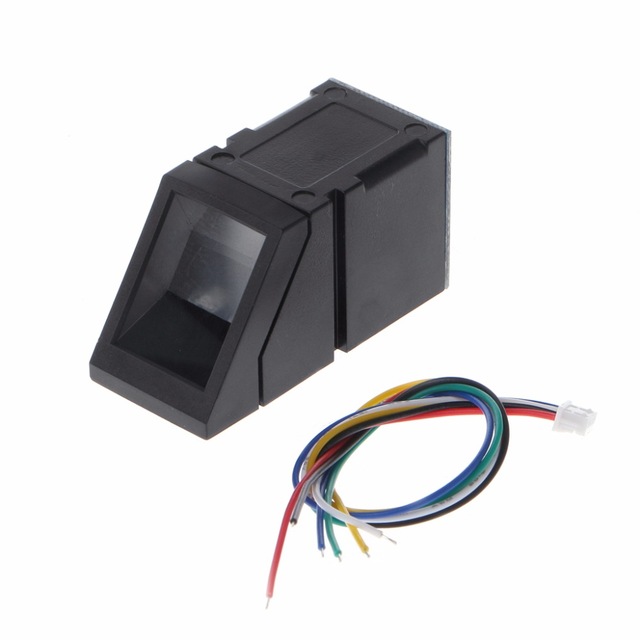
- Fingerprint Sensor: Verifies the citizen after candidate selection
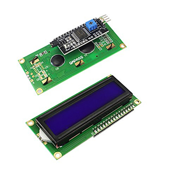
- I2C LCD Display: Displays instructions and voting status
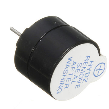
- Buzzer: Provides audio feedback for successful or invalid operations
- Jumper Wires: Connect components to the ESP32 board
- Breadboard: Organizes and connects components
Wiring and Connection Guide
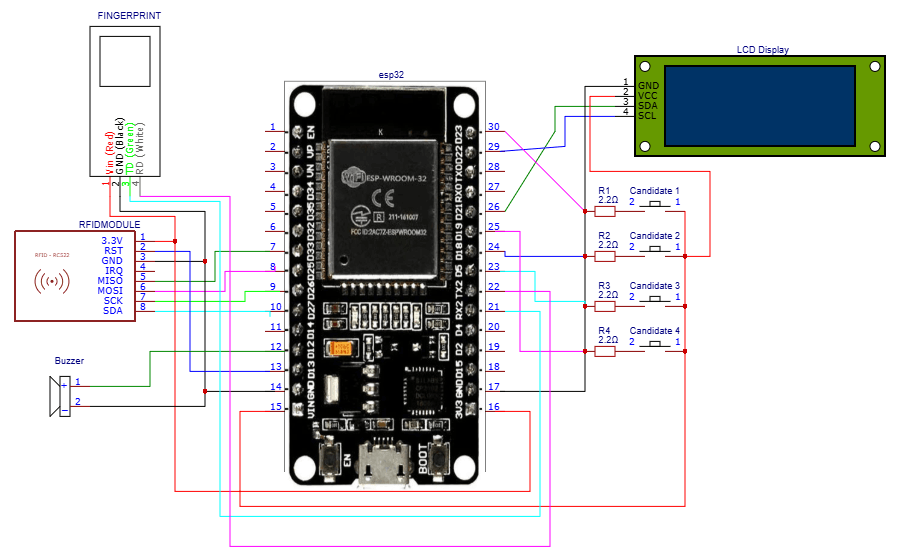
To connect the components, start by placing the ESP32 board on the breadboard. Connect the MFRC522 RFID module to the ESP32 board by linking the VCC pin of the RFID module to the 3.3V pin on the ESP32, the GND pin to any GND pin on the ESP32, the RST pin to any digital pin on the ESP32 (for example, pin 22), the MISO pin to the MISO pin on the ESP32, the MOSI pin to the MOSI pin on the ESP32, the SCK pin to the SCK pin on the ESP32, and the SDA pin to any digital pin on the ESP32 (for example, pin 21). Next, connect the 4 push buttons to the ESP32 board. Each push button should have one leg connected to a digital pin on the ESP32 (for example, pins 23, 19, 18, and 5) and the other leg connected to the GND pin on the ESP32. Then, connect the fingerprint sensor to the ESP32 board. The VCC pin of the fingerprint sensor should be connected to the 3.3V pin on the ESP32, the GND pin to any GND pin on the ESP32, the RX pin to the TX pin on the ESP32 (for example, pin 17), and the TX pin to the RX pin on the ESP32 (for example, pin 16). After that, connect the I2C LCD display to the ESP32 board. The VCC pin of the LCD display should be connected to the 3.3V pin on the ESP32, the GND pin to any GND pin on the ESP32, the SDA pin to any digital pin on the ESP32 (for example, pin 21), and the SCL pin to any digital pin on the ESP32 (for example, pin 22). Finally, connect the buzzer to the ESP32 board by linking the positive leg of the buzzer to any digital pin on the ESP32 (for example, pin 25) and the negative leg to the GND pin on the ESP32.| Component | ESP32 Pin |
|---|---|
| MFRC522 VCC | 3.3V |
| MFRC522 GND | GND |
| MFRC522 RST | 22 |
| MFRC522 MISO | MISO |
| MFRC522 MOSI | MOSI |
| MFRC522 SCK | SCK |
| MFRC522 SDA | 21 |
| Push Button 1 | 23 |
| Push Button 2 | 19 |
| Push Button 3 | 18 |
| Push Button 4 | 5 |
| Fingerprint Sensor VCC | 3.3V |
| Fingerprint Sensor GND | GND |
| Fingerprint Sensor RX | 17 |
| Fingerprint Sensor TX | 16 |
| LCD Display VCC | 3.3V |
| LCD Display GND | GND |
| LCD Display SDA | 21 |
| LCD Display SCL | 22 |
| Buzzer Positive Leg | 25 |
| Buzzer Negative Leg | GND |
🛠️ Step-by-Step Guide
Step 1: Setting Up the Development Environment
To start building the ESP32-based electronic voting system, you need to set up your development environment. This includes installing the Arduino IDE, which supports ESP32 boards, and the necessary libraries for the hardware components used in this project. Ensure you have the latest version of the Arduino IDE installed on your computer.
Step 2: Preparing the Hardware Components
Gather all the hardware components: ESP32 board, RFID (MFRC522) module, Push Buttons (4), Fingerprint Sensor, I2C LCD Display, and a Buzzer. Make sure all components are compatible with the ESP32 board and are in working condition.
Step 3: Wiring the Components
Wire all the components to the ESP32 board according to their respective pinouts. The RFID module typically uses SPI pins, the Push Buttons use digital input pins, the Fingerprint Sensor uses serial communication (UART), the I2C LCD Display uses I2C pins, and the Buzzer uses a digital output pin. Ensure all connections are secure and not loose.
A brief wiring recap: - RFID (MFRC522) to ESP32: SCK to GPIO18, MOSI to GPIO23, MISO to GPIO19, CS to GPIO5 - Push Buttons to ESP32: Each button to a separate digital input pin (e.g., GPIO32, GPIO33, GPIO25, GPIO26) - Fingerprint Sensor to ESP32: TX to GPIO17, RX to GPIO16 - I2C LCD Display to ESP32: SCL to GPIO22, SDA to GPIO21 - Buzzer to ESP32: To a digital output pin (e.g., GPIO13)
Step 4: Writing and Uploading the Firmware
Using the Arduino IDE, write the firmware for the ESP32 board that integrates all the components' functionalities. Include libraries for the RFID module, Fingerprint Sensor, and I2C LCD Display. The code should handle the two-factor authentication (RFID and Fingerprint) and the voting logic. After writing the code, upload it to the ESP32 board.
Step 5: Testing the System
Test each component and the overall system to ensure everything works as expected. Start by testing the RFID module for successful authentication, then the Push Buttons for candidate selection, followed by the Fingerprint Sensor for voter verification. Finally, test the voting process to ensure it records votes correctly and displays the status on the I2C LCD Display. The Buzzer should provide feedback for successful or invalid operations.
A testing checklist: - RFID authentication - Push Button functionality - Fingerprint verification - Voting process - I2C LCD Display updates - Buzzer feedback
Step 6: Troubleshooting Tips
If you encounter any issues during the setup or testing phase, refer to the following troubleshooting tips: - Check all connections for security and correctness. - Ensure the power supply is adequate for all components. - Verify that the firmware is correctly uploaded and the ESP32 board is properly reset. - Use serial debugging to monitor the system's status and identify any errors. - Consult the datasheets and documentation for each component for specific troubleshooting guides.
💻 Sample Code
#include <Arduino.h>
#include <MFRC522.h>
#include <Wire.h>
#include <LiquidCrystal_I2C.h>
#include <Adafruit_Fingerprint.h'

// Define pins for RFID module
#define RST_PIN 22
#define SS_PIN  5

// Define pins for push buttons
#define BUTTON1_PIN 13
#define BUTTON2_PIN 12
#define BUTTON3_PIN 14
#define BUTTON4_PIN 27

// Define pins for fingerprint sensor
#define FINGERPRINT_TX_PIN 17
#define FINGERPRINT_RX_PIN 16

// Define pins for buzzer
#define BUZZER_PIN 25

// Define LCD display address
#define LCD_ADDRESS 0x27

MFRC522 mfrc522(SS_PIN, RST_PIN);
LiquidCrystal_I2C lcd(LCD_ADDRESS, 16, 2);
Adafruit_Fingerprint fingerprints = Adafruit_Fingerprint(FINGERPRINT_TX_PIN, FINGERPRINT_RX_PIN);

// Function to initialize RFID module
void initRFID() {
  SPI.begin();
  mfrc522.PCD_Init();
}

// Function to read RFID card
void readRFID() {
  if (!mfrc522.PICC_IsNewCardPresent()) return;
  if (!mfrc522.PICC_ReadCardSerial()) return;
  // Get UID of the card
  byte *uid = mfrc522.uid.uidByte;
  byte uidSize = mfrc522.uid.size;
  // Authenticate the card
  if (uidSize != 4) return;
  byte expectedUID[4] = {0x12, 0x34, 0x56, 0x78}; // Replace with your expected UID
  bool isValid = true;
  for (int i = 0; i < uidSize; i++) {
    if (uid[i] != expectedUID[i]) {
      isValid = false;
      break;
    }
  }
  if (!isValid) return;
  // Start voting process
  lcd.setCursor(0, 0);
  lcd.print("Voting started");
}

// Function to handle push button press
void handleButtonPress(int buttonPin) {
  // Read the state of the button
  int buttonState = digitalRead(buttonPin);
  if (buttonState == HIGH) {
    // Select candidate based on button pressed
    if (buttonPin == BUTTON1_PIN) {
      lcd.setCursor(0, 1);
      lcd.print("Candidate 1");
    } else if (buttonPin == BUTTON2_PIN) {
      lcd.setCursor(0, 1);
      lcd.print("Candidate 2");
    } else if (buttonPin == BUTTON3_PIN) {
      lcd.setCursor(0, 1);
      lcd.print("Candidate 3");
    } else if (buttonPin == BUTTON4_PIN) {
      lcd.setCursor(0, 1);
      lcd.print("Candidate 4");
    }
    // Verify voter's identity using fingerprint sensor
    verifyFingerprint();
  }
}

// Function to verify fingerprint
void verifyFingerprint() {
  // Get fingerprint image
  int fingerprintResult = fingerprints.getImage();
  if (fingerprintResult != FINGERPRINT_OK) {
    lcd.setCursor(0, 1);
    lcd.print("Fingerprint error");
    return;
  }
  // Convert image to template
  fingerprintResult = fingerprints.image2Tz(1);
  if (fingerprintResult != FINGERPRINT_OK) {
    lcd.setCursor(0, 1);
    lcd.print("Fingerprint error");
    return;
  }
  // Compare template with stored template
  fingerprintResult = fingerprints.compareFinger();
  if (fingerprintResult != FINGERPRINT_OK) {
    lcd.setCursor(0, 1);
    lcd.print("Fingerprint error");
    return;
  }
  // If fingerprint matches, record vote
  recordVote();
}

// Function to record vote
void recordVote() {
  // Save vote to database or flash memory
  lcd.setCursor(0, 0);
  lcd.print("Vote recorded");
  // Provide audio feedback
  tone(BUZZER_PIN, 1000, 500);
}

void setup() {
  Serial.begin(115200);
  // Initialize RFID module
  initRFID();
  // Initialize LCD display
  lcd.init();
  lcd.backlight();
  // Initialize fingerprint sensor
  fingerprints.begin(57600);
  if (!fingerprints.verifyPassword()) {
    lcd.setCursor(0, 0);
    lcd.print("Fingerprint sensor error");
    while (true);
  }
  // Initialize push buttons
  pinMode(BUTTON1_PIN, INPUT);
  pinMode(BUTTON2_PIN, INPUT);
  pinMode(BUTTON3_PIN, INPUT);
  pinMode(BUTTON4_PIN, INPUT);
  // Initialize buzzer
  pinMode(BUZZER_PIN, OUTPUT);
}

void loop() {
  // Check for RFID card presence
  readRFID();
  // Check for push button press
  handleButtonPress(BUTTON1_PIN);
  handleButtonPress(BUTTON2_PIN);
  handleButtonPress(BUTTON3_PIN);
  handleButtonPress(BUTTON4_PIN);
  delay(100);
}
📝 Check Your Understanding
1. What is the primary function of the RFID module in the ESP32-based electronic voting system?
   a) To verify the citizen's fingerprint
   b) To display voting instructions and status
   c) To initialize and authenticate the voting session
   d) To provide audio feedback
   Answer: c

2. Which of the following components is responsible for providing audio feedback in the voting system?
   a) I2C LCD Display
   b) Push Buttons
   c) Fingerprint Sensor
   d) Buzzer
   Answer: d

3. What is the purpose of the two-factor authentication in the voting system?
   a) To allow multiple voters to vote at the same time
   b) To verify the voter's identity before recording the vote
   c) To select a candidate
   d) To display voting results
   Answer: b

4. How many push buttons are used in the ESP32-based electronic voting system?
   a) 2
   b) 3
   c) 4
   d) 5
   Answer: c

5. What is the role of the I2C LCD Display in the voting system?
   a) To authenticate the voter using RFID
   b) To verify the voter's fingerprint
   c) To display instructions and voting status
   d) To record the vote
   Answer: c
Need the Components for This Project?
If you don't already have the components listed above, you can buy genuine Arduino, ESP32, Raspberry Pi, sensors, and other electronic components from SoftTech Supply Shop, with fast delivery across Kigali and other parts of Rwanda.
← Browse more Arduino & IoT tutorialsRelated Tutorials
How to build an ESP32-based door access control system using keypad for password authentication
ESP32 ESP-32 Wireless WiFi Bluetooth Development Board, 4 * 4 Matrix Array Matrix Keypad, SG90 9g Mini Micro Servo Motor, 16x2LCD Display with I2C Interface, 3MM LED Red
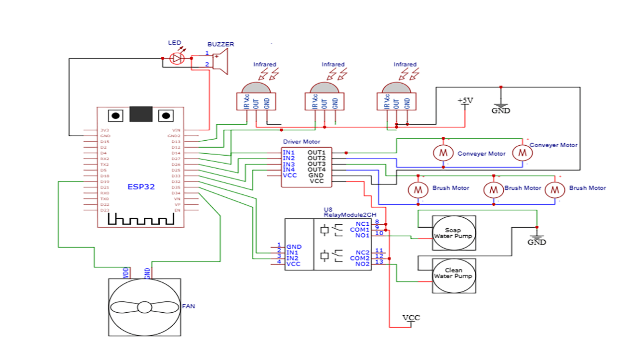
How to build ESP32-based automatic car wash system
The hardware components used in the automatic car wash system include one, ESP32 Development Board (ESP32-WROOM-32 DevKit), Infrared Obstacle Avoidance Tracking Sensor Module, L298N Motor Driver, Single Channel 5v Relay Module, SUBMERSIBLE WATER PUMP DC 3V-5V, YD8010 Cooling Fan 5V, 3MM LED Red, 5V active buzzer, 5V 2A Power Adapter, 12VDC 2A Adapter charger, Male to Male Jumper Wires, Breadboard 830 Point Solderless, terminal blocks or connectors, one main power switch, one fuse for power protection, and mounting hardware such as screws, nuts, and standoffs.
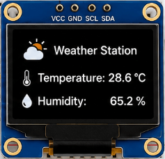
Build a Wi-Fi Weather Station with ESP32
ESP32 ESP-32 Wireless WiFi Bluetooth Development Board, DHT22 Digital Temperature & Humidity Sensor Module, 0.96" Inch Blue I2C IIC OLED LCD Module4pin, Breadboard 830 Point Solderless, Male to Female jumper wires
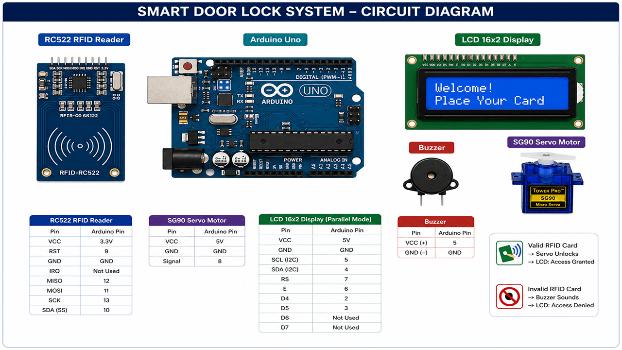
Smart Door Lock with RFID and Servo Motor
Arduino UNO R3 removable IC Chip with USB CABLE, RFID Reader Module 13.56Mhz, SG90 9g Mini Micro Servo Motor, 16x2LCD Display with I2C Interface, 5v active buzzer, Breadboard 830 Point Solderless, Male to Male Jumper Wires