How to build an ESP32-based door access control system using keypad for password authentication
📖 Overview
This course will guide you through the process of building a door access control system using an ESP32 board, a 4x4 keypad, a servo motor, an I2C LCD, and three LED indicators. By the end of this course, you will have a fully functional system that can authenticate users based on a password and grant or deny access to a door.
Throughout this course, you will learn how to interface the ESP32 with various hardware components, including the keypad, servo motor, and LCD display. You will also learn how to write code in C++ to control the system, including reading password input from the keypad, verifying the password, and controlling the servo motor and LEDs. Additionally, you will learn how to use the I2C communication protocol to display messages on the LCD.
The skills and knowledge you gain from this course will be useful in a variety of applications, including home automation, security systems, and IoT projects. You will learn how to design and build a secure and reliable access control system, and how to integrate multiple hardware components into a single system. Some of the key topics covered in this course include:
- ESP32 board and its features
- Keypad interface and password authentication
- Servo motor control and door locking mechanism
- I2C communication protocol and LCD display
- LED indicators and system status display
This course is designed for intermediate-level students who have some experience with microcontrollers and programming. By the end of this course, you will have a deep understanding of how to design and build a door access control system using an ESP32 board and various hardware components. You will also have the skills and knowledge to apply this knowledge to other projects and applications.
🔌 Components & Wiring Guide
Components and Their Purposes
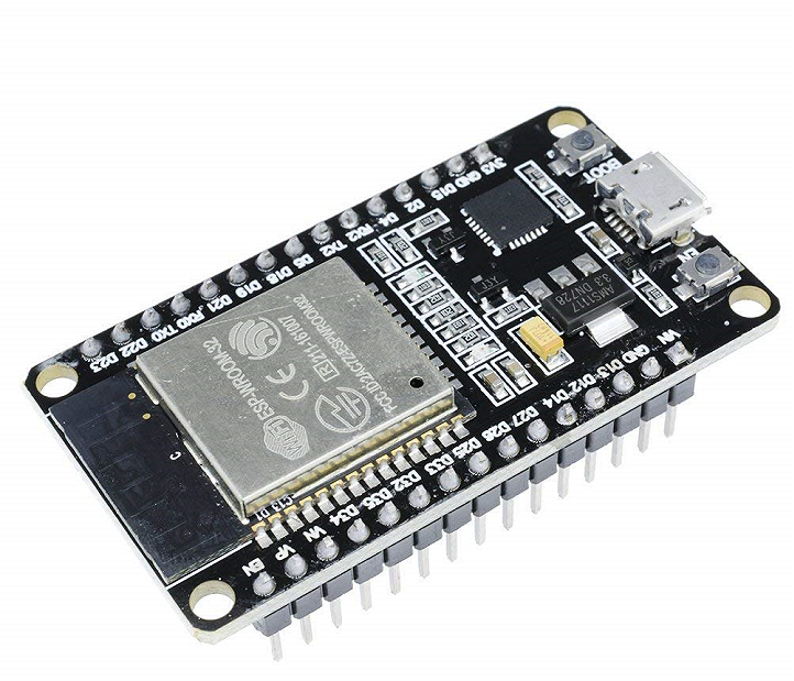
- ESP32: Main controller of the system, responsible for processing user input and controlling other components.
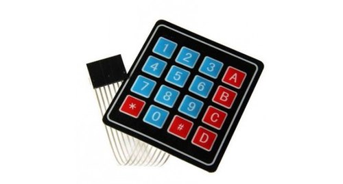
- 4×4 Keypad: Allows users to enter passwords for door access.
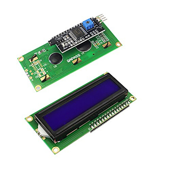
- I2C LCD Display: Displays system messages and status updates to the user.
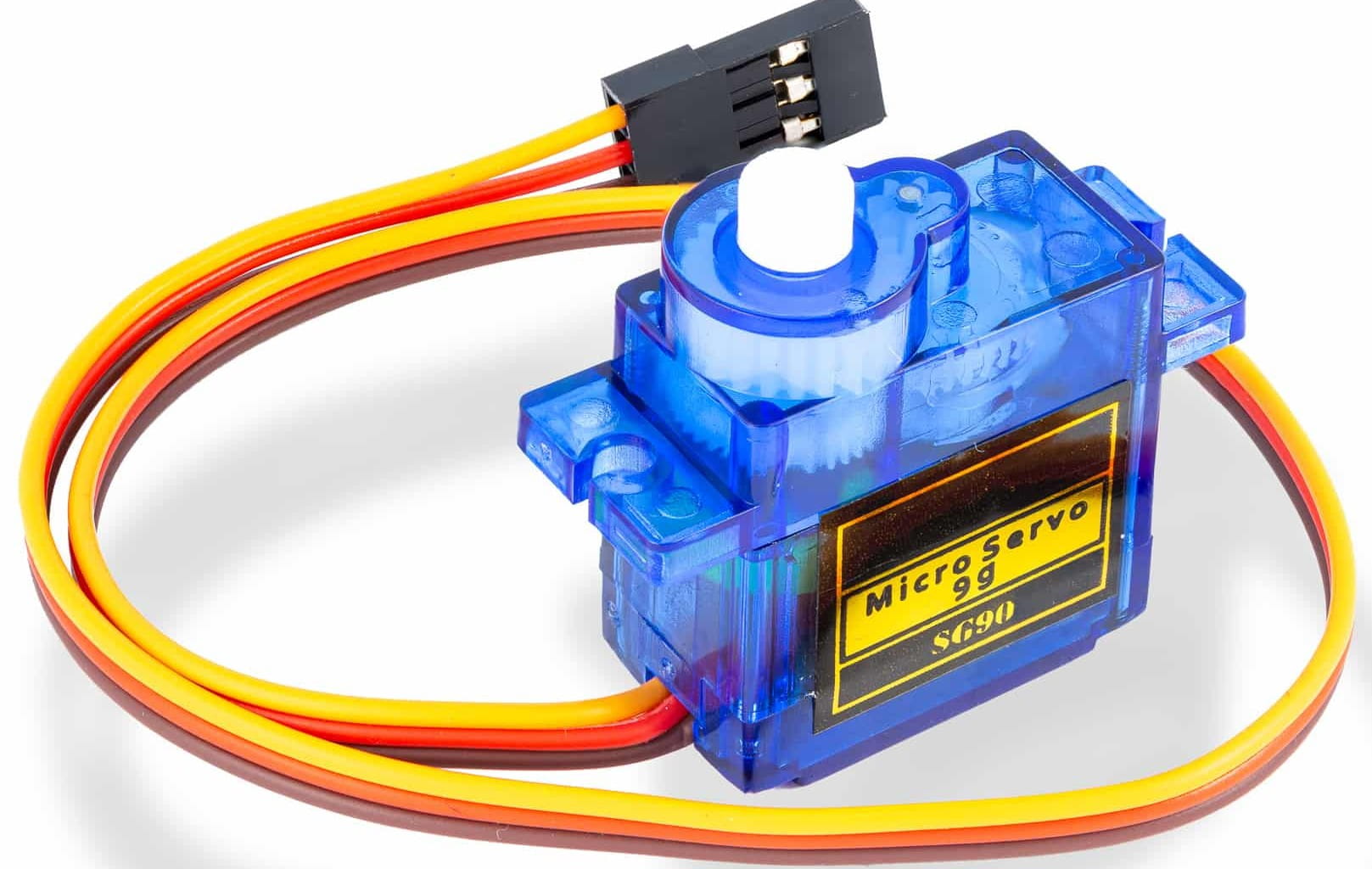
- Servo Motor: Controls the locking and unlocking of the door.
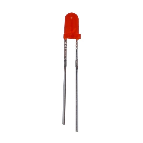
- LED Indicators (Green, Red, Yellow/Blue): Provide visual feedback on the system's status and user input.
- Current-limiting Resistors: Protect the LEDs from excessive current.
- 5V Power Supply: Powers the ESP32, LCD, keypad, and servo motor.
Wiring and Connection Guide
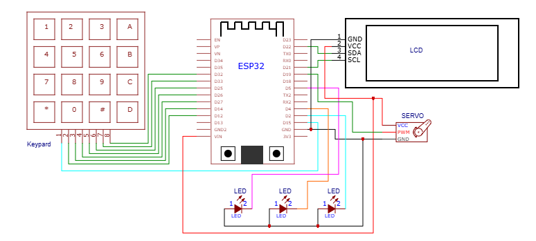
To connect the components, follow these steps: Connect the 4×4 keypad to the ESP32 by linking the keypad's four row connections to four digital GPIO pins on the ESP32 (e.g., GPIO 0-3) and the four column connections to another four digital GPIO pins (e.g., GPIO 4-7). Next, connect the I2C LCD display to the ESP32 using the I2C communication protocol: link the LCD's GND to the ESP32's GND, VCC to the ESP32's 3.3V or 5V, SDA to the ESP32's SDA pin, and SCL to the ESP32's SCL pin. Then, connect the servo motor to the ESP32: link the servo's VCC to a 5V supply, GND to the common ground, and the signal wire to a PWM-capable GPIO pin on the ESP32 (e.g., GPIO 16). After that, connect the LED indicators to the ESP32: link the positive terminal of each LED to a separate digital GPIO pin (e.g., GPIO 17, 18, 19) and the negative terminal to the common ground through a current-limiting resistor. Finally, power the ESP32, LCD, and keypad using a 5V supply connected to the ESP32's VIN pin or USB port, and power the servo motor from the same 5V supply or a separate regulated 5V supply if it draws significant current.Procuring the Components
If you don't already have the necessary components, you can purchase them from SoftTech Supply at https://softechsupply.com/shop/.🛠️ Step-by-Step Guide
Introduction to the ESP32-Based Door Access Control System
This tutorial guides you through building a door access control system using an ESP32, a 4x4 keypad, a servo motor, an I2C LCD, and three LED indicators. The system allows for password authentication, with the ESP32 serving as the central controller.
Setting Up the Hardware Components
Before starting the build, ensure you have all the necessary components: ESP32, 4x4 keypad, servo motor, I2C LCD, three LED indicators, a 5V power supply, and a USB cable for programming the ESP32.
Wiring the Components
Connect the components according to the following wiring diagram:
- Keypad: Connect the four row and four column connections to eight GPIO pins on the ESP32.
- I2C LCD: Connect GND to ESP32 GND, VCC to ESP32 3.3V or 5V, SDA to ESP32 SDA pin, and SCL to ESP32 SCL pin.
- Servo Motor: Connect VCC to 5V supply, GND to common ground, and PWM (Signal) to ESP32 PWM-capable GPIO pin.
- LED Indicators: Connect each LED to a separate GPIO output pin on the ESP32, with the negative terminal connected to the common ground through a current-limiting resistor.
Writing and Uploading the Firmware
Write the firmware code using a suitable IDE, such as Arduino IDE or PlatformIO, and upload it to the ESP32. The code should include functions for reading the keypad input, verifying the password, controlling the servo motor, and updating the LCD display.
Example code snippet: const char* password = "1234";
Uploading the Firmware to the ESP32
Connect the ESP32 to your computer using a USB cable and upload the firmware code. Ensure the ESP32 is in bootloader mode before uploading the code.
Testing the System
After uploading the firmware, test the system by entering the password using the keypad. If the password is correct, the green LED should turn on, the servo motor should rotate to unlock the door, and the LCD should display "Access Granted."
- Enter the correct password and verify that the system unlocks the door and displays the correct message.
- Enter an incorrect password and verify that the system remains locked and displays "Access Denied."
- Test the system with different passwords and verify that it functions as expected.
Troubleshooting Tips
If the system does not function as expected, check the following:
- Verify that all connections are secure and correct.
- Check the firmware code for errors and ensure it is uploaded correctly.
- Test the individual components, such as the keypad, servo motor, and LCD, to ensure they are functioning correctly.
- Adjust the servo motor's PWM signal and angle to ensure it is rotating correctly.
Conclusion and Future Enhancements
With this tutorial, you have successfully built an ESP32-based door access control system using a keypad for password authentication. You can further enhance the system by adding features such as Wi-Fi connectivity, remote access, and multiple user accounts.
💻 Sample Code
#include <WiFi.h>
#include <LiquidCrystal_I2C.h>
#include <Servo.h>

// Define constants
const int KEYPAD_ROWS = 4;
const int KEYPAD_COLS = 4;
const int KEYPAD_ROW_PINS[] = {13, 12, 14, 27};
const int KEYPAD_COL_PINS[] = {26, 25, 33, 32};
const int SERVO_PIN = 15;
const int GREEN_LED_PIN = 2;
const int RED_LED_PIN = 0;
const int YELLOW_LED_PIN = 4;
const int LCD_ADDRESS = 0x27;
const int LCD_CHARS = 16;
const int LCD_LINES = 2;
const char* STORED_PASSWORD = "1234";

// Define variables
char enteredPassword[5];
int passwordIndex = 0;
bool doorUnlocked = false;
Servo servo;
LiquidCrystal_I2C lcd(LCD_ADDRESS, LCD_CHARS, LCD_LINES);

void setup() {
  // Initialize serial communication
  Serial.begin(115200);

  // Initialize keypad pins
  for (int i = 0; i < KEYPAD_ROWS; i++) {
    pinMode(KEYPAD_ROW_PINS[i], OUTPUT);
  }
  for (int i = 0; i < KEYPAD_COLS; i++) {
    pinMode(KEYPAD_COL_PINS[i], INPUT);
  }

  // Initialize servo
  servo.attach(SERVO_PIN);
  servo.write(0); // Initialize servo to locked position

  // Initialize LEDs
  pinMode(GREEN_LED_PIN, OUTPUT);
  pinMode(RED_LED_PIN, OUTPUT);
  pinMode(YELLOW_LED_PIN, OUTPUT);
  digitalWrite(YELLOW_LED_PIN, HIGH); // Turn on yellow LED to indicate power

  // Initialize LCD
  lcd.init();
  lcd.backlight();
  lcd.setCursor(0, 0);
  lcd.print("Enter Password");

  // Initialize door state
  doorUnlocked = false;
}

void loop() {
  // Read keypad input
  for (int row = 0; row < KEYPAD_ROWS; row++) {
    digitalWrite(KEYPAD_ROW_PINS[row], HIGH);
    for (int col = 0; col < KEYPAD_COLS; col++) {
      if (digitalRead(KEYPAD_COL_PINS[col]) == HIGH) {
        // Key press detected, add to entered password
        char key = getKeyPressed(row, col);
        if (key != '\0') {
          if (passwordIndex < 4) {
            enteredPassword[passwordIndex] = key;
            passwordIndex++;
          }
          if (passwordIndex == 4) {
            // Password entry complete, verify password
            verifyPassword();
          }
        }
      }
    }
    digitalWrite(KEYPAD_ROW_PINS[row], LOW);
  }

  // Delay to prevent excessive keypad scanning
  delay(50);
}

char getKeyPressed(int row, int col) {
  // Map keypad row and column to key value
  char keys[KEYPAD_ROWS][KEYPAD_COLS] = {
    {'1', '2', '3', 'A'},
    {'4', '5', '6', 'B'},
    {'7', '8', '9', 'C'},
    {'*', '0', '#', 'D'}
  };
  return keys[row][col];
}

void verifyPassword() {
  // Compare entered password with stored password
  if (strcmp(enteredPassword, STORED_PASSWORD) == 0) {
    // Password correct, unlock door
    digitalWrite(GREEN_LED_PIN, HIGH);
    servo.write(90); // Unlock door
    lcd.setCursor(0, 0);
    lcd.print("Access Granted");
    delay(2000);
    servo.write(0); // Lock door after delay
    digitalWrite(GREEN_LED_PIN, LOW);
  } else {
    // Password incorrect, deny access
    digitalWrite(RED_LED_PIN, HIGH);
    lcd.setCursor(0, 0);
    lcd.print("Access Denied");
    delay(1000);
    digitalWrite(RED_LED_PIN, LOW);
  }
  // Reset password entry
  passwordIndex = 0;
  lcd.setCursor(0, 0);
  lcd.print("Enter Password");
}
Need the Components for This Project?
If you don't already have the components listed above, you can buy genuine Arduino, ESP32, Raspberry Pi, sensors, and other electronic components from SoftTech Supply Shop, with fast delivery across Kigali and other parts of Rwanda.
← Browse more Arduino & IoT tutorialsRelated Tutorials
Build simple project with arduino
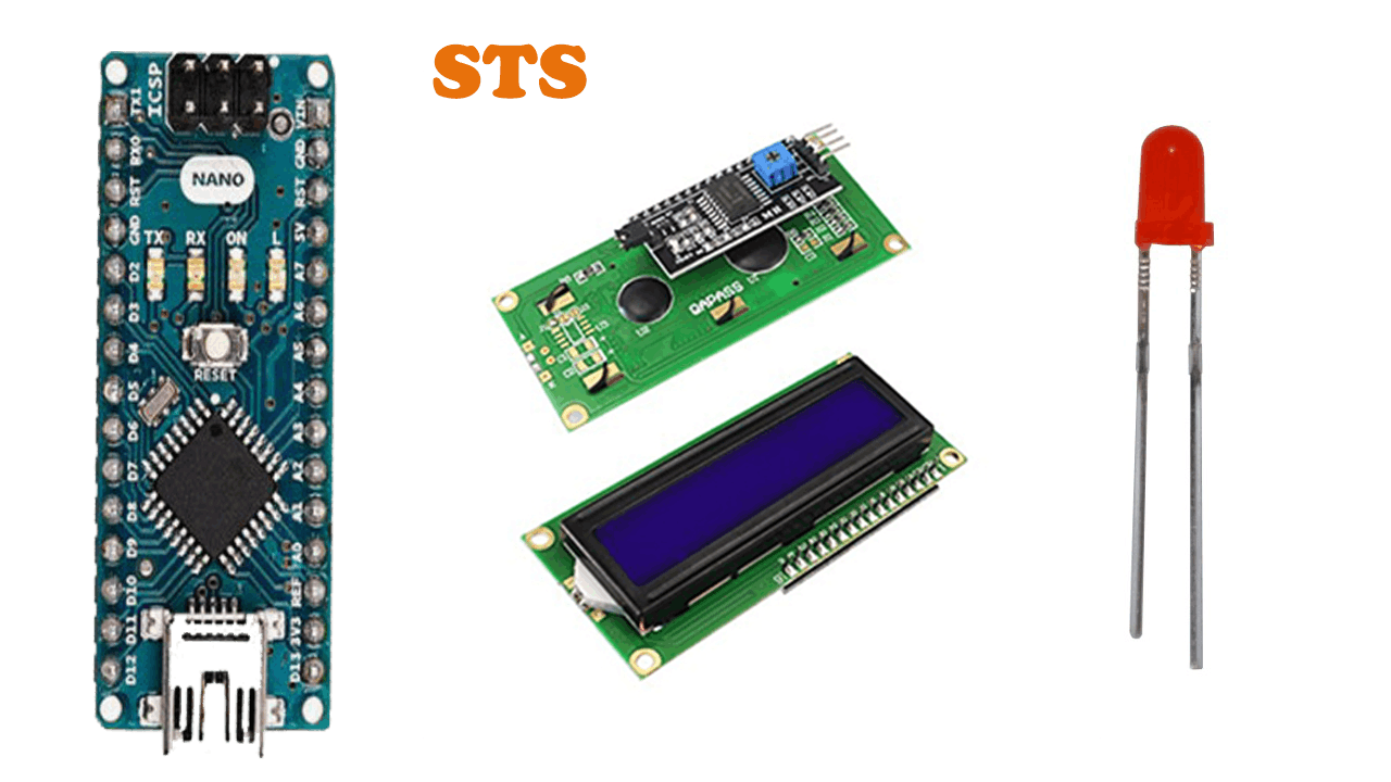
Arduino Nano + Cable, 16x2LCD Display with I2C Interface, 3MM LED Red
How to connect esp32 on WiFi
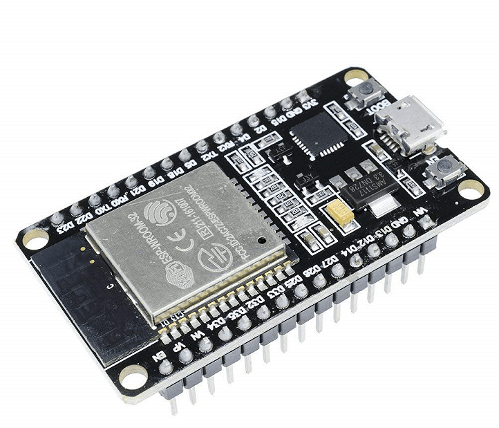
ESP32 ESP-32 Wireless WiFi Bluetooth Development Board, smartphone, or any other device that can shared WiFi
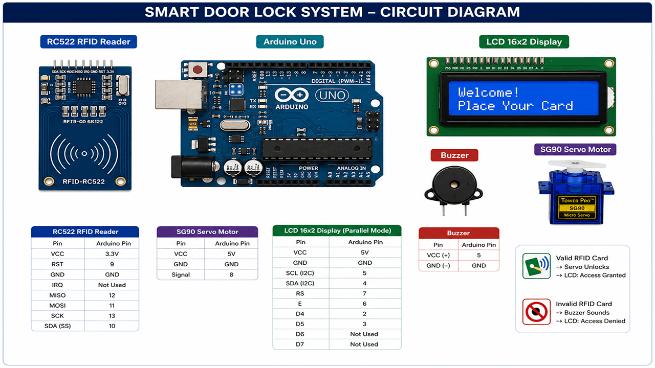
Smart Door Lock with RFID and Servo Motor
Arduino UNO R3 removable IC Chip with USB CABLE, RFID Reader Module 13.56Mhz, SG90 9g Mini Micro Servo Motor, 16x2LCD Display with I2C Interface, 5v active buzzer, Breadboard 830 Point Solderless, Male to Male Jumper Wires
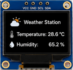
Build a Wi-Fi Weather Station with ESP32
ESP32 ESP-32 Wireless WiFi Bluetooth Development Board, DHT22 Digital Temperature & Humidity Sensor Module, 0.96" Inch Blue I2C IIC OLED LCD Module4pin, Breadboard 830 Point Solderless, Male to Female jumper wires