DSO2C10 Digital Oscilloscope Dual Channel
Price:
RWF 545,000Added to Cart!
Need help or have questions about this product?
Contact STS Support →Product Description
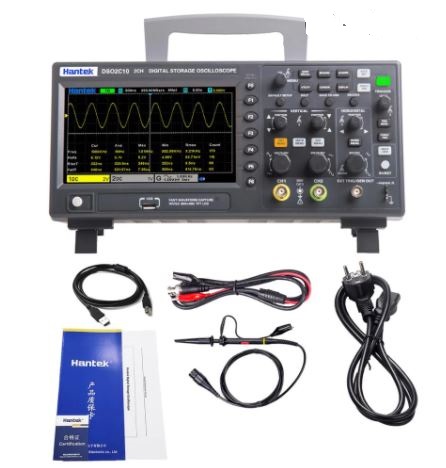
The DSO2C10 Digital Oscilloscope is a dual-channel oscilloscope designed for accurate signal analysis and testing. With a 100 MHz bandwidth and a sampling rate of up to 1 GSa/s, it provides high-resolution and precise waveforms for a wide range of applications, from electronics testing to troubleshooting. The oscilloscope features a clear 7-inch color display, allowing users to easily visualize waveforms and perform real-time signal analysis. This compact and portable instrument is equipped with advanced features like automatic measurements, waveform storage, and a USB interface for data transfer.
The DSO2C10 is an excellent choice for those seeking a high-performance yet affordable oscilloscope for everyday use in laboratories, workshops, and field applications. It is ideal for engineers, hobbyists, and professionals who need a reliable tool for debugging and testing analog and digital circuits.
Specifications:
- 100 MHz bandwidth
- Up to 1 GSa/s sampling rate
- Dual-channel design for simultaneous signal analysis
- 7-inch color display for clear waveform visualization
- Automatic measurements and waveform storage
- USB interface for data transfer
Applications:
- Electronics testing and troubleshooting
- Robotics and automation
- Sensor testing and calibration
- Arduino and ESP8266 project development
- Lab and field testing for engineers and hobbyists
- Education and research institutions
The DSO2C10 Digital Oscilloscope is a versatile and reliable tool for anyone working with electronic circuits and signals. Its high-performance capabilities, compact design, and affordable price make it an ideal choice for a wide range of applications.
Why Buy from SoftTech Supply?
- Genuine electronic components from trusted suppliers
- Competitive prices on Arduino, Raspberry Pi, sensors & more
- Fast delivery across Kigali and Rwanda
- Expert technical support and project consultation
- Easy returns and quality guarantee
Related Products
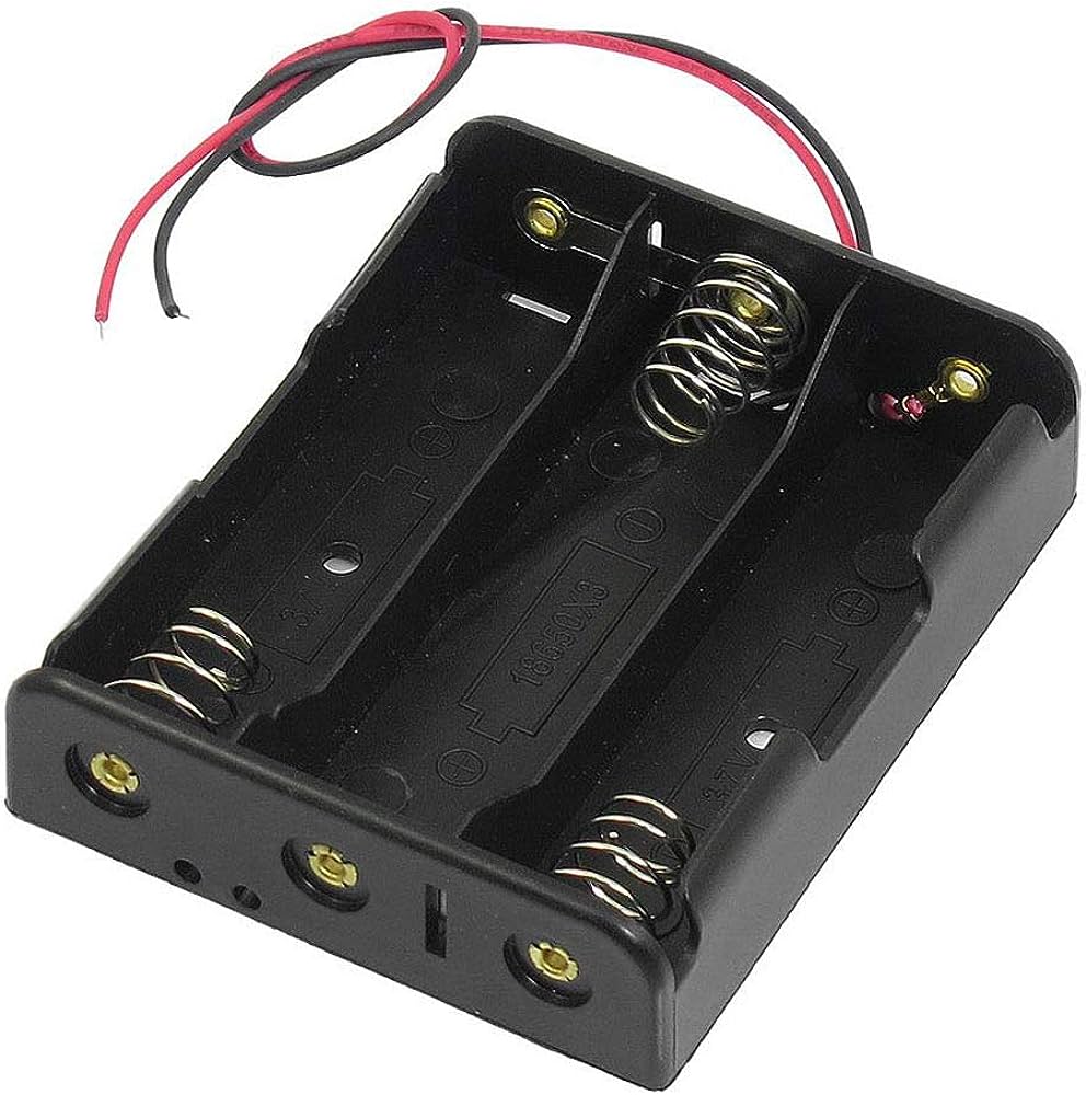
3.7V 3 Slot 18650 Battery holder
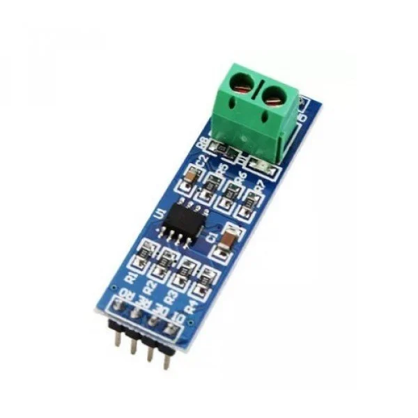
HW-097 MAX485 TTL to RS485 Modbus Module
Buy DSO2C10 Digital Oscilloscope Dual Channel at STS - Kigali, Rwanda
DSO2C10 Digital Oscilloscope Dual Channel is available at SoftTech Supply, your trusted electronics shop in Kigali, Rwanda. We stock genuine electronic components including Arduino boards, Raspberry Pi, ESP32, ESP8266, various sensors, motors, displays, and thousands of other components for your IoT, embedded systems, and electronics projects. Visit our shop or order online for fast delivery across Rwanda. Need help selecting components or implementing your project? Contact STS for expert technical support and consultation.